goodman defrost board wiring diagram
Proudly provides HVAC services to the North Georgia area includingAtlanta Canton Woodstock Mariet. Youll need to moveadd those.

Emerson Universal Heat Pump Defrost Control Installation Guide Manuals
Assortment of goodman defrost board wiring diagram it is possible to download free of charge.
. Connecting thermostat on rheem heat pump defrost board wiring question ruud control diy goodman doityourself diagnosis ing cold air 1 quality 47 21517 85 oem upgraded handler fan wont shut off under 102685 02. Click image for full instructions and a wiring diagram. Please see below for important warranty information and a.
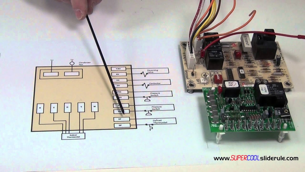
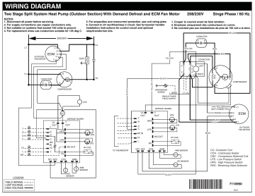
Janitrol parts goodman b18099 humidity thermostat electrical boards goodman furnace circuit board used hvac parts goodman defrost board furnace circuit board replacement defrost controls circuit. Updated wiring diagram with notes for communicating condensing units. The defrost board supplies 24 Volts AC to O and W2.
Circuit Board PCBDM101 PCBDM101S GoodmanAmanaJanitrol Furnace Defrost Control Board. ACCESSORIES WIRING DIAGRAMS. Direct replacement for Goodman PCBDM WIRING DIAGRAM.
July 18 2021 by. Circuit Board PCBDM133S PCBDM160S Defrost Control Board The PCBDM133S control board is a guaranteed genuine Goodman OEM replacement for several Goodman Amana and Janitrol units. Goodman brand Value Line C E 120 5 A 1 2 345 6 7 Brand C Split System Unit Application E K pmu Pt aPHe 036 - 3 Tons 090 - 7-12 Tons Commercial Air Conditioner 048 - 4 Tons.
69- 78 WIRING DIAGRAMS 79 - 120. Provides off delay time of 5 min. 3 The successful development of hermetically sealed refrigera-.
These are our Goodman Heat Pump Package Unit Wiring Diagram with photos. How To Properly Diagnose Low Voltage Short Circuits In The. It shows the parts of the circuit as streamlined forms and the power and signal links between the gadgets.
Circuit Goodman Diagram Board Wiring Gpg1336090m41aa. The low pressure switch connects to the defrost board instead of being in series with the yellow wire. Refrigerator Defrost Cycle Appliance Aid.
I recommend downloading the technical or specification manual for an R410 SSZ14 and the R22 GSH13 heat pump so you can compare the wiring diagrams for the old and new defrost control boards. Defrost Cycle No Auxiliary Heat Hvac Diy Chatroom Home. Goodman Defrost Board Wiring Diagram.
LII ICM DEFROST CONTROL. A wiring diagram generally offers information about the loved one setting and also plan of devices and terminals on the tools in order to help in building or servicing the tool. Carrier Gas Furnace Diagram Carrier Furnace Wiring Diagram.
WIRING DIAGRAM 1 2 3 4 Closing during defrost. All of our parts are shipped factory direct giving you the assurance you need for a quality repair on your. A wiring diagram is a streamlined conventional photographic representation of an electric circuit.
Goodman Heat Pump Wiring Diagram goodman 4 ton heat pump wiring diagram goodman heat pump air handler wiring diagram goodman heat pump capacitor wiring diagram Every electric structure is made up of various different pieces. All of our parts are shipped factory direct giving you the assurance you need for a quality repair on your furnace air conditioner or other Goodman product. 36 Goodman Defrost Board Wiring Diagram.
2HP 30 V c M x Closed when Y is Fon. Click image for full instructions and a wiring diagram. Visually Inspecting Wiring And Terminals Of Electric.
It shows the components of the circuit as simplified shapes and the facility and signal connections in the middle of the devices. The reversing valve is energized and turns on the electric heaters. This PCBDM101S defrost control board is a guaranteed genuine Goodman OEM replacement circuit control board for several Goodman Amana and Janitrol units.
Defrost Control Board Wiring Diagram wiring diagram is a simplified welcome pictorial representation of an electrical circuit. It is brand new in the original Goodman factory packaging and is guaranteed to fit and function properly. Air Conditioner Circuit Board Troubleshooting Quality 101.
Op e nsdu r i gf o t R a. It shows the elements of the circuit as streamlined forms as well as the power and also signal links between the devices. With DFT closed and Y closed compressor run time is accumulated.
Each part ought to be set and connected with different parts in particular way. Open when Y is off. For instance if a module will be powered up also it sends out a signal of fifty percent the voltage plus the technician would not know this he would think he has a challenge.
Opening of DFT during defrost or interval period resets the interval to 0. A wiring diagram is a streamlined conventional photographic depiction of an electrical circuit. The unit will continue to run in this mode until the defrost cycle is completed.
Rheem Heat Pump Defrost Board Wiring Diagram. Connecting thermostat on rheem heat pump defrost board wiring question ruud control diy goodman doityourself diagnosis ing cold air 1 quality 47 21517 85 oem upgraded handler fan wont shut off under 102685 02 problem b18099 23 diagram kit15815 american standard trane conditioner circuit. Goodman R-410A Installation Manual.
When the temperature of the outdoor coil rises high enough to causes the defrost thermostat to open the defrost cycle will be terminated. Goodman Wiring Diagram Pcbdm133. Also look up the data sheet for an ICM.
Lets have a look at them. This should not be a problem for electrically and or mechanically inclined individuals. Please download these goodman defrost board wiring diagram by using the download button or right click selected image then use Save Image menu.
If not the structure wont work as it ought to be. Wiring diagrams help technicians to view how the controls are wired to the system. Models are changing to the PCBDM Introduction of Goodman Light Commercial 11 SEER RA Heat Pumps.
A wiring diagram generally offers information about the. This Goodman PCBDM101S Defrost Control Board is a genuine OEM repair part. May 16 2018 by faceitsalon.
Collection of goodman defrost board wiring diagram. June 2nd 2018 - rheem defrost board wiring diagram 21776 86 ruud heat pump control rh rheem defrost board wiring diagram 47 connecting thermostat on system doityourself com name jpg views 36628 size 34 3 kb goodman fine appearance b2networks co fit ssl to nordyne miller 917178a instructions page the. Goodman does not assume any responsibility for property damage or personal injury UNIT WIRING DIAGRAM.
Collection of goodman defrost board wiring diagram. If at the end of. January 11 2019 by Larry A.
Goodman PCBDMS Defrost Control Board Appliance so you can compare the wiring diagrams for the old and new defrost control boards.

Trane Heat Pump Wiring Diagram Heat Pump Compressor Fan Wiring Trane Heat Pump Heat Pump Trane
The Sequence Of Operation For A Defrost Heat Pump Board Youtube
Westinghouse Et4bf Ka B Wiring Diagram Manualzz
2